Some of the measures described below require opening your DS series sensor to make adjustments. Most sensors will have both high voltage supplying the sensor itself and high voltage being switched by the load contactor(s).
![]() REMOVE ALL SENSOR AND
CONTROLLED POWER BEFORE OPENING THE FRONT COVER!
REMOVE ALL SENSOR AND
CONTROLLED POWER BEFORE OPENING THE FRONT COVER!![]()
If your question is not covered please call us at 719-599-7477 or e-mail us at: trouble@goase.com
The precipitation sensor on a DS unit clears itself by evaporating the rain or snow that lands on it. Over time, minerals and contaminates can be left behind by the evaporation process. This can also be caused by testing the sensor using a liquid other than clear water. Soda or saliva are not good substitutes! ASE recommends that the sensor grid be cleaned with water and a non-metallic (Scotch-Brite™ or equivalent) cleaning pad about every 4 months. Replacement sensor heads can also be ordered for significantly less than the cost of an entire DS unit and are very easy to replace.
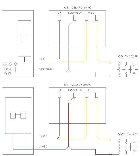
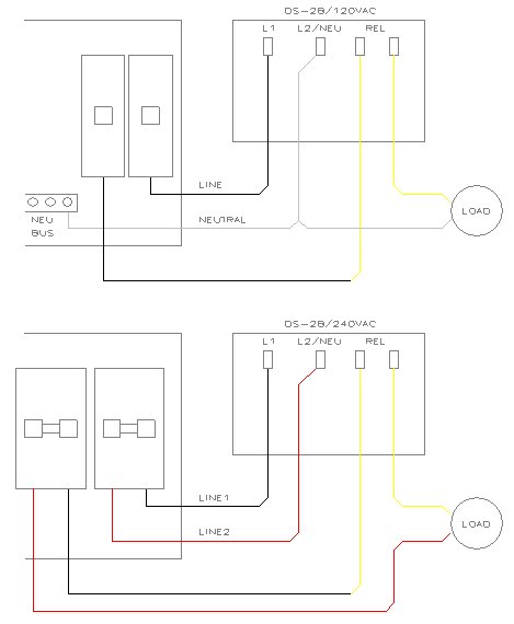
The relay in your sensor acts like a switch or a thermostat. One of the load leads must be connected to your voltage source and, when the relay closes, the voltage will come out the other lead. While this may seem more complicated this gives you LOTS of flexibility in controlling your loads. You can operate the DS unit from one voltage and control a load with a different voltage. You can operate your low current load from the same breaker used to supply the DS unit or separate the feeds for protecting the DS unit with a low current breaker but feeding your load from a high current breaker. You can power the DS unit from 120VAC or 240VAC and control 24VAC loads.
The diagram on the left shows typical wiring for low current control where a contactor is switched and the contactor coil shares the same power feed as the DS unit. The diagram on the right shows examples of controlling the load using a separate breaker for high current loads or different voltages. You can also control a "thermostat" style load by connecting the load directly to the two yellow leads.
Always check with a licensed electrician and observe local codes when creating your control scheme.
These sensors contain configuration switches that allow the sensor to operate properly for the application. This is what gives the unit flexibility. Improper settings can also be the cause of unexpected operation. Check the manual included with the unit (or reference the on-line manual) and confirm that the switches are set correctly for your application. Note, too, that any configuration switch changes must be followed by a power down/power up cycle for the change to become effective!
A special note for DS-4 users! The index mark on the rotary switch is the small arrow at a right angle to the screwdriver slot, not the screwdriver slot itself.
A special note for DS-2B/DS-5 users! Observe the "ON" position of the configuration switches. These may be going toward or away from the legends. The "ON" legend printed on the switch indicates the correct "ON" position.
If you have a sensor fitted with a front or side panel override switch you can move it to the Standby/Reset position, then back to the Automatic position. This will clear the delay-off timer. If a DP-7B/EX is connected you can also switch it to Standby/Reset, then back to Automatic.
All DS series sensors can be fitted with optional control and monitor cable(s). The leads can be connected either to a DP-7B/EX, CDP-2 or to your own control/monitor equipment. On all control cables the White lead is digital ground. Connecting the Black lead to the White lead will place the unit into Manual On. Connecting the Green lead to the White lead will place the unit into Standby/Reset. You can connect these leads using a dry contact closure, an optoisolator, or a simple switch. If both leads are connected to the White lead at the same time Standby/Reset will take precedence.
The monitor contacts will close when the main load contactor closes. This dry contact can carry up to 24VDC/VAC, up to 500 mA, but no more than 10 W.
A special note for DS-4/DS-4C/DS-7C users! Check the profile sheet included with your sensor for the actual function of your Black, Green, Red, and Orange control leads. Functions are profile-dependent.
Your DS-2B, DS-4, or DS-5 may be configured for LTC or Low Temperature Cutoff. LTC is requested by some manufacturers in order to inhibit triggering of the deicing system below 15ºF. The assumption is that snow at very low temperatures tends to be very dry and should not be a problem. However, this is not always the case. Check the LTC switch on your DS-2B or DS-5 and switch it off if you wish to defeat low temperature cutoff. Most DS-4 profiles offer a configuration with LTC and a companion without LTC. Select the appropriate companion. Again, remember to power down, then power back up if a configuration switch is changed.
This can be a tough question to answer but a number of tests can be performed to narrow down the problem.
First, remove any connected remote control and monitor cabling. Confirm that the distant end leads of these cables are properly terminated and are not touching any metal surfaces or other leads.
Is the precipitation grid getting hot? This indicates that power is making it to the unit. If not, check the on-board fuse and the input power wiring.
Is the unit strapped for the correct input power? Running 240VAC into a unit strapped for 120VAC will normally blow the fuse and cause a cool precipitation grid. However, running 120VAC into a unit strapped for 240VAC will warm the grid but not allow the unit to operate.
Turn the Delay adjustment down to the 9 o'clock position. This is a forced Manual On position. The load contactor should close. Return the Delay adjustment to its original position. The load contactor should open. The DS-4 will respond according to its profile but at least Relay 1 should close. If the unit will not pass this test it is defective.
Wet snow tends to fall at elevated temperatures. Though it may be above freezing outside the colder upper atmosphere may allow snow to form. This occurs regularly in high altitude locations. This is why the center position for Trigger Temperature is 39ºF rather than 32ºF. Try adjusting the Trigger Temperature higher. Also make sure your sensor is not mounted in a location near exhaust hoods or other sources of heat.
You may need to adjust your Delay Off cycle longer to allow the deicing system to clear all of the snow and dry the surface. The Delay adjustment 12 o'clock position is 30 minutes moving to 90 minutes at 3 o'clock. If this does not cure the problem or if snow removal is patchy check to see if the deicing system itself is working properly.
In many installations the heating system is supplied by a different breaker than the one supplying the sensor. Confirm that this load breaker is closed. Some systems also use a high current contactor controlled by the sensor load contactor. If installed, confirm that this contactor is working properly and that any included thermal overloads are not tripped. Some antenna heaters employee an in-line thermostat for controlling the actual operating temperature of the heater panels.
The presence of a gray enclosure mounted to the wall may
not be pleasing in a residential setting. A couple different methods may be used
to mask the presence of the DS unit
 without
compromising its proper operation.
without
compromising its proper operation.
The user may fabricate a "cover" in a material that matches the exterior of the building. The cover should consist of two sides and a front. The front of the cover should be mounted to the sides in a manner that allows easy removal for access to the controller. It is also recommended that sufficient room be left on the right side of the cover to allow access to the manual override switch. The top of the cover must remain open to allow an unobstructed view of the sky in order for the precipitation sensor to detect rain and snow. The bottom must also be left open to allow free air circulation for proper temperature sensing and to prohibit the build-up of snow or other materials against the base of the controller.
The enclosure can also be painted with a finish compatible
with PVC. An example would be Krylon® Fusion for Plastic® or Rust-Oleum® Paint
for Plastic paint. However, the precipitation sensor must be properly
masked to avoid any overspray on the sensing grid. The override switch handle
and boot should also be masked to assure proper operation. It is also
recommended that the front cover label be masked so that pertinent information,
user warnings, electrical ratings, and the UL and CE logo's not be covered. Be
sure to mask the indicator lamp lens on the DS-8.
![]()
For More Information, Contact
Automated Systems
Engineering, Inc.
2519 E Saint Vrain Street
Colorado Springs, Colorado, USA 80909
Phone: 719-599-7477 FAX: 719-599-7482
![]() info@goase.com
info@goase.com
We accept all major credit cards!


![]()
Home
DS Sensors GFPE DP-7B
CDP-2 EX-50
Cable
Sets Parts
Manuals Troubleshooting
Best if viewed at 1024 x 768 or higher
This site is copyright 1998-2015 by Automated Systems Engineering, Inc.
Comments about the website? Please contact webmaster@goase.com
Last Update: 03/25/16